The Elaboration Phase
The elaboration phase of the tailored version of PosoMAS focuses mainly on design activities, detailing the following aspects:
- The system architecture and how the agents, external systems, and the environment are structured.
- The individual agent architecture and the design of each type of agent.
- The organisational structure in which the agents are embedded and the self-organisation algorithm that creates that structure.
- The interactions between the individual agents, between agent organisations, and between the system and its environment.
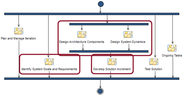
Activities specific to PosoMAS are indicated in red.
Advantages of PosoMAS
The method content for the elaboration phase sees the most dramatic extension over the standard OpenUP. PosoMAS offers activities, tasks, and guidelines for all aspects of the system design. In addition, goal-driven requirements elicitation is still present and the implementation work is extended with specific tasks for the creation of model transformations. Since PosoMAS is more specific than the very generic OpenUP, this additional content gives a system designer and the developers much additional support. The tasks captured in the activities, the steps described in the tasks, the additional guidelines, and the description of relevant concepts guide the development team in all stages of the design. A special focus on PosoMAS is on reuse, with dedicated tasks and much information on agent implementation patterns, reusable protocols, and architectural styles. The bibliography provided with PosoMAS and the examples given in the process description are excellent starting points for discovering existing solutions in the literature. The aids provided by PosoMAS to (semi-)automatically incorporate an Observer/Controller infrastructure allow the development team to rapidly introduce adaptive behaviour into the system.
Iterations: Iteration 1 | Iteration 2
Iteration 1
Plan and Manage Iteration
As in each iteration, an Iteration Plan was prepared. The main objectives were taken from the Project Plan and evaluation criteria were defined. Since the iteration was mainly focused on refining the architectural vision defined during the Inception phase, design activities were in the foreground, as witnessed by the objectives. However, the main evaluation criterion was the preparation of a prototype, capable of basic scheduling. This reflects the agile principle that each iteration should yield a tangible artefact that is of value for the customer. In addition, the scheduling functionality has been identified as the crucial element for project success.
The Work Items List was refined at the start of Iteration 1 by replacing the generic work item category "Design Agent Organisation and System Architecture" with the more specific requirement that drives the design of agent organisation and system architecture, namely the need for a suitable structure of AVPPs. In addition, priorities and effort estimations were assigned for the relevant work items scheduled for the iteration.
The assessment of the iteration after the work was done showed that, again, the effort was underestimated. While all work items were completed, 1.5 additional man hours were required to do so. The main reason were the design activities for scheduling that required more time than anticipated. An additional issue was discovered during the phase: the weather stations had initially been modelled as agents of the system since they are necessary to provide proper weather forecasts for the stochastic producers. During the elaboration, however, the team along with the Product Owner decided that weather data can be bought from external vendors so that weather stations are no longer agents in the system but rather elements of the system environment that are engaged through a well-defined interface. This decision has been recorded in the Iteration Plan and is reflected in the design artefacts.
| Activities and Tasks | Work Products |
|
|
Identify System Goals and Requirements
While a number of high-impact goals and requirements were already identified in the inception phase, others that play a more supporting role have been left out. Most prominently, the system goal "Maintain[Suitable AVPP Structure]" was identified but not elaborated further. Therefore, goals that specify what "suitable" means in this context and appropriate obstacles were defined in a separate Goal Diagram. Since the selection of an agent organisation and corresponding self-organisation algorithm was postponed from the Inception to the Elaboration (see below) these goals directly inform the design activities in this phase. Other goals were not refined at this stage in the process. System limitations and constraints were not identified at this point either. The Glossary and the Conceptual Domain Model remained unchanged as well.
| Activities and Tasks | Work Products |
|
Design Architecture Components
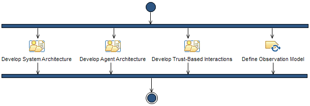
The first iteration of the Elaboration phase is very much focused on the design of the different areas of the architecture. The Design Architecture Components whose work breakdown structure can be seen in Figure 2 captures all "static" elements of the architecture and combines tasks and activities defined in a number of PosoMAS practices. These activities are not scheduled to happen sequentially and will in all likelihood be tackled in parallel due to their interconnected nature.
The main activities are accompanied by two tasks that span all three activities:
- Develop System Architecture in which the high-level architecture, the relationship to systems in the environment, and the environmental factors are considered and appropriate architectural styles are applied.
- Develop Agent Architecture in which the individual architecture of the agents is designed based on existing implementation patterns.
- Develop Trust-based Interactions in which the infrastructure required to deal with uncertainties on the basis of a trust-model is developed.
- Define Observation Model in which a model is designed that defines how feedback loops are embedded in the system to ensure adaptive behaviour.
- Refine the Architecture in which all aspects of the architecture are refined based on new requirements or additional knowledge about the system.
The resulting design documents are all captured in the Architecture Notebook that becomes the main tool to document and communicate design decisions and models. The system architecture had already been captured in the Inception phase. However, weather stations were defined as system-internal in the inception. Discussions and a closer scoping of the project revealed that external systems can be used to provide weather forecasts and the appropriate component was therefore changed to only contain elements denoted with the «predefined» stereotype.
The Conceptual Domain Model is refined to a true design class diagram. An architectural style is applied by making use of the reference architecture proposed in (Anders et al., 2013) that proposes a number of elements that play a role in the domain. The external systems are made a part of the design class diagram and operations are defined that describe their interface, e.g., WeatherStation.getWeatherForecast(). The model is also expanded with elements that become necessary due to added requirements. A number of attributes, such as schedulingMaximumThreshold, are introduced to deal with the goals that refine the goal "Maintain[Suitable AVPP Structure]" as discussed in Design System Dynamics. The hierarchical structure of the system also motivates the definition of a number of OCL constraints that define a "top-level AVPP" and that each GenericPowerPlant has to be the child of an AVPP (except the top-level AVPP).
The design of the individual agent progresses mostly as part of the overall design class diagram. At this moment, no specialised diagrams for the agents are created. It is, however, up to the designer to capture the design of the different types of agents in individual models and diagrams.
The System Goals Document contains the goal "Measure systematic deviations from predictions". It implies that the error that is made by stochastic power plants in the prediction of their future output has to be measured and the predictions corrected if such a systematic error can be detected. Clearly, such an error introduces uncertainty in the system. Develop Trust-based Interactions has been devised to deal with such uncertainties. It proposes to decompose interactions prone to uncertainty in one interaction that defines a contract, either implicitly or explicitly stating the desired outcome of the interaction, and an interaction that fulfils the contract. In our case, the prediction maps to the first interaction since it defines the expected outcome. The actual production of power is then the interaction that fulfils the contract. Deviations between the prediction and the actual production can be measured and a Trust Model can be applied to measure the credibility of the power plant. This value can then be taken into account when scheduling, i.e., the expected deviation from the prediction can be used to schedule additional reserves. While a reputation system is not required in the system under construction, some trust management infrastructure has to be introduced. We apply the "Direct Trust Pattern" from (Anders et al., 2013): it specifies the decomposition of an interaction as described above, introduces abstractions for a trust metric to calculate trust values, and defines a context in which an interaction took place (e.g., the time of day can play a role in the accuracy of predictions for solar power plants). All relevant elements of the pattern are specialised by classes specific to power management. The resulting architecture is depicted in the design class diagram in the Architecture Notebook.
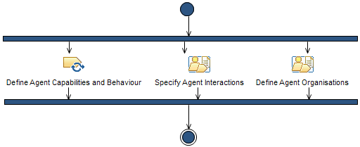
The dynamics of the system encompass the agent behaviour, the interactions between agents, and the formation of agent organisations. These aspects are therefore captured in a common activity, depicted in Figure 3. In the simulated development effort, little focus was put on identifying agent capabilities and distinct behaviours. These aspects are more important if there are a variety of agent types with very different behaviour or when, e.g., BDI is used to implement the agents. The BDI multi-agent framework Jadex, e.g., supports a form of heredity through capabilities, collections of goals, plans, beliefs, and messages. If Jadex is used as an implementation platform, identifying capabilities that are common to the different agent types can be helpful in using this abstraction in the actual implementation. Likewise, if the agents show complex behaviour, it is beneficial to model it appropriately. As an example of such a model, the Architecture Notebook contains a state chart for the HiSPADA algorithm (see below) taken from (Steghöfer et al., 2013). The specification of agent interactions consists of the definition of interfaces, data types, and protocols. In addition, the use of predefined interaction patterns is promoted in PosoMAS. The design class diagram contains specific classes for the exchange of information, e.g., PowerPrediction and WeatherForecast. Operations that can be called by other agents through messaging are denoted with the «external» stereotype that is part of the PosoMAS Auxiliary UML Profile. If complex protocols are used to negotiate or coordinate certain actions, sequence diagrams and state charts are useful for their specification. The Architecture Notebook contains a sample interaction for the creation of schedules that shows the interactions between the different agents in the creation of new schedules. The development team made the decision to fold the Agent Interaction Model into the Architecture Notebook to keep all information in the same place. The task Apply Patterns to Agent Interactions suggests the use of the FIPA Interaction Protocols. The main focus with regard to system dynamics in this first iteration of the Elaboration phase was the decision for an agent organisation and the selection of a suitable self-organisation algorithm. The goals that refine "Maintain[Suitable AVPP Structure]" the need for an agent organisation that takes the time required for scheduling and the different types of power plants into account. Groups of power plants should be able to calculate schedules on their own. However, the number of individual groups of power plants has to be kept in check due to the coordination effort between the groups. Since one of the non-functional requirements is to create a system that scales to large numbers of power plants, a hierarchical approach seems sensible. The different organisational structures in (Horling & Lesser, 2004) are checked for suitability and identified in the Agent Organisation Structure document. This work product also shows the relevant requirements and the selected self-organisation algorithms, described in (Steghöfer et al., 2013). They create groups of agents by applying an anti-clustering in which clusters are similar externally but heterogeneous externally and use an additional control loop that takes scheduling times into account to create a hierarchy. An activity chart describing this control loop has been included in the Architecture Notebook. The first iteration of the Elaboration phase does not yet consider the observation model that specifies how system state is monitored and how this information is used in a feedback loop to control the system. The task will feature more prominently in the second iteration. The Refine Architecture task captures all design activities not included in the specific PosoMAS elements and applies, e.g., to the specific design of the back end, the data classes, or other, not MAS-specific elements of the design. The Develop Solution Increment activity has been changed in PosoMAS to incorporate model transformations that allow the developers to transform the design model augmented with an observation model into the implementation of an Observer/Controller infrastructure that implements the feedback loops that control the system. These tasks will be tackled later in the process and are therefore not described at this point. Since implementation was not part of the simulated development effort, no further work was done in this activity. Further activities not tackled at this point are Test Solution and Ongoing Tasks. The former instructs the developers in the definition of test cases and test scripts and the implementation of system tests and will play a role in a later iteration. The latter deals with change requests that occur during the iteration. The original Project Plan proposed a total duration for the second iteration of the Elaboration phase of 2.5h. As evident from the Iteration Plan, this relatively short time span could be further reduced to 1.75h. This is mainly due to the fact that it was possible to reuse a lot of prior work as detailed in the sections on the design of the system further below. The Work Items List shows the focus of the iteration, consistent with the objectives in the Iteration Plan: refinement of the trust-based interactions, specification of the self-organisation algorithm, and work towards the code generation for the implementation of feedback loops. At the same time, the requirement "Maintain[Network Frequency]" to guarantee a stable power grid even when unforeseen events occur, has been tackled. As in the previous iteration, the main artefact that has been updated was the Architecture Notebook. The System Goals Model has been updated as well. The refinement of the system goals in this iteration focused on the task Define System Limitations and Constraints which has been ignored so far. Its purpose is to add a formal description of the constraints described by the requirement that can later be used to check the requirements against the implementation or, as will be described later, to generate code to observe the constraints at runtime. As an example, the requirement "Network frequency compared to optimal frequency" that contributed to the goal "Maintain[Frequency Stability]" has been refined this way, using an OCL-expression: context ControllablePowerPlant inv The constraint noFrequencyDeviations is valid for all instances of the class ControllablePowerPlant and uses the class' attributes currentFrequency, optimalFrequency, and allowedDeviation to define an invariant. These attributes are reflected in the design class diagram that is part of this iteration's Architecture Notebook as well. The invariant ensures that the network frequency — a function of the difference of power production and consumption — stays within a certain corridor defined by allowedDeviation. If the invariant is violated the system has to react appropriately, e.g., by producing more power. This is the reason why the constraint is only relevant for instances of ControllablePowerPlant: only these power plants are able to adjust their output to accommodate the network frequency. Similar invariants have been defined for the requirements "Observe minimum scheduling time" and "Observe maximum scheduling time" that both contribute to the goal "Maintain[Suitable AVPP Structure]". These define the limitations of the time required for scheduling as discussed above. The system can react to violations of these invariants by changing the system structure and introducing new hierarchy levels or resolving existing ones. The goal "Maintain[Suitable AVPP Structure]" has also been refined to reflect the chosen agent organisation and the hierarchical self-organisation picked in the previous iteration. While this iteration sees mostly a refinement of existing design models the Observation Model is added to the Architecture Notebook. This artefact defines how the state of the individual agents is observed and reacted upon. It can make use of the constraints defined in the System Goals Model and allows a controller to make use of the observed state and of the check of the invariants defined for the different agent types. As such, control loops are introduced into the system with the Observation Model and adaptive behaviour now enters the design. We use the observation model from (Eberhardinger et al., 2013) that is based on the Observer/Controller architectural pattern (Richter et al., 2006) and incorporates constraints into the monitoring. It uses publish/subscribe to allow controllers to register with the observer for the violation of certain constraints. This allows different controllers to react to different violations, making it possible to define rather fine-grained behaviour. The observation model uses a dedicated State Model to communicate the state of an agent to the observer. The state model should be a serialisable data class, only holding the relevant state of an agent at a certain point in time. Again, publish/subscribe is used to register an observer with the agent which then informs the observer whenever the state changes. In highly volatile systems, such an approach could lead to an overwhelmed observer and much communication overhead, so a polling approach might be more suitable. For the present system, however, this "push" is sufficient. In comparison to the previous iteration, the attributes and associations have been refined to reflect the requirements and new information. Furthermore, getOutputPrediction() has been moved to GenericPowerPlant. A controllable power plant can thus make predictions as well, e.g., when it is relocated to a different AVPP and the AVPP needs to know what the power plant can reasonably produce in the next time steps. The integration of the trust infrastructure has been improved as well. There is now one PowerDeliveryContract per PowerPrediction and multiple PowerPredictions can be part of one PowerDeliveryContract. Design work for the "Maintain[Network Frequency]" goal was limited. The development team decided that sensor infrastructure would not be explicitly modelled in the design diagrams. Instead, the ControllablePowerPlant has corresponding attributes that reflect the current sensor data and is updated whenever the value is requested. The NetworkFrequencySensor is, however, added to the high-level diagram as part of a Grid Sensors component. Part of the implementation activities is the creation of model transformations that allow the developers to automatically generate design artefacts from the requirements specification and code from the design artefacts. Such a process is described in (Eberhardinger et al., 2013) for the semi-automatic transformation of the constraints captured in the System Goals Model to an observation model as shown in the Architecture Notebook and then further to platform-specific code. The transformations developed as part of the work for the paper mentioned above use QVT, with the generic observation model as a pre-specified view and yield a UML class diagram. The transformation from the specialised observation model into code can then be performed by using the Xpand language. Due to the focus of the iteration on the inclusion of the observation model and the preparation for model transformations, Develop System Dynamics, Test Solution, and Ongoing Tasks have been largely ignored. The system dynamics will be considered again in the Construction phase. Likewise, testing will be considered there.
This material is made available under the Creative Commons—Attribution-ShareAlike License v3.0.
© Copyright 2013, 2014 by Institute for Software & Systems Engineering, University of Augsburg
Activities and Tasks
Work Products
Design System Dynamics
Activities and Tasks
Work Products
Develop Solution Increment
Other Activities
Iteration 2
Plan and Manage Iteration
Activities and Tasks
Work Products
Identify System Goals and Requirements
noFrequencyDeviations: abs(currentFrequency - optimalFrequency) < allowedDeviation
Activities and Tasks
Work Products
Design Architecture Components
Activities and Tasks
Work Products
Develop Solution Increment
Activities and Tasks
Work Products
Other Activities
Bibliography
Copyright
Contributors
Contact: Jan-Philipp Steghöfer